Cranes often play a central role in animations, used to help visualise lifts and deployment methodologies with checks on reach, hook height and rigging design. Accurate and practical 3D models are vital, with many being created based on existing 2D AutoCAD type views (plans and elevations). At times, there is less source information available and in those cases older scanned PDFs are used with references to photos to help with the modelling process. Newer forms of source information include laser surveys and point clouds, where millions of data points are stored electronically and can be viewed at a later date for measurements and general reference.
Below are some examples of how these 3D cranes can be created in often a short amount of time, resulting in extremely valuable assets that can be used in supporting engineering projects.
1. Traditional, orthographic views as a source
The most common starting point for crane modelling has been with standard 2D CAD views coming from AutoCAD. These drawings are supplied as part of a package of drawings alongside vessel general arrangements. Ideally, crane curves are also supplied to confirm the technical spec of the crane and its physical capabilities. The CAD drawings are tidied up and imported to Autodesk 3ds Max where they can be checked for real world scale and aligned in 3D space before modelling.
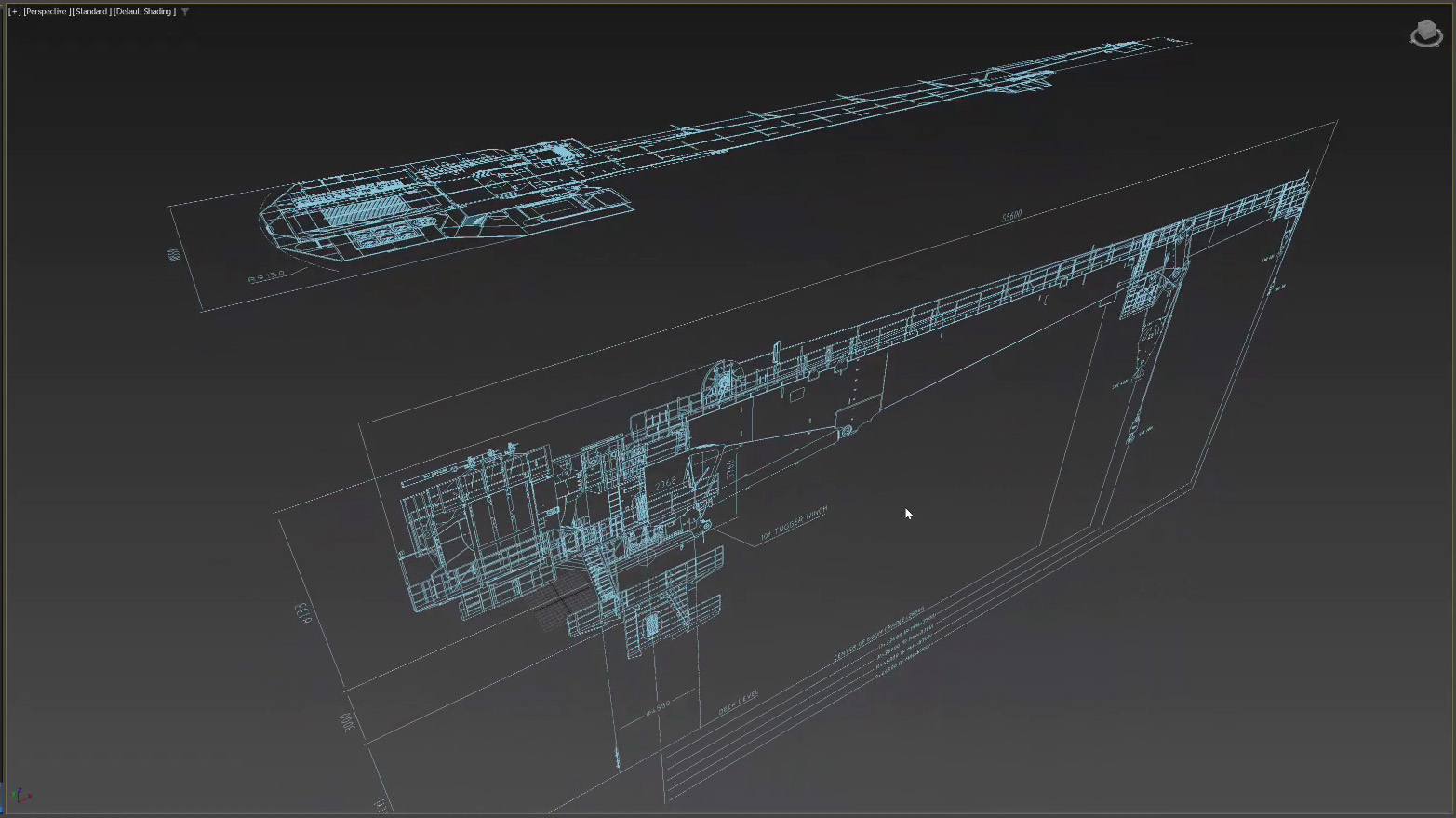
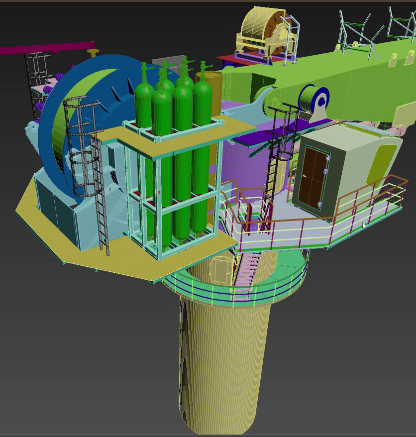
There are varying degrees of detail that can be used in modelling these cranes, but often the best approach is to set a budget (in time) and generate what is visually adequate as well as functionally accurate without focussing on smaller details. The main pivot points and rigging locations are what matters, and this is where the real value comes in. A very simple representation of a crane can be created with basic shapes but if the connection points and pivots are all accurate then the model will behave as required in those vital engineering checks and procedures.
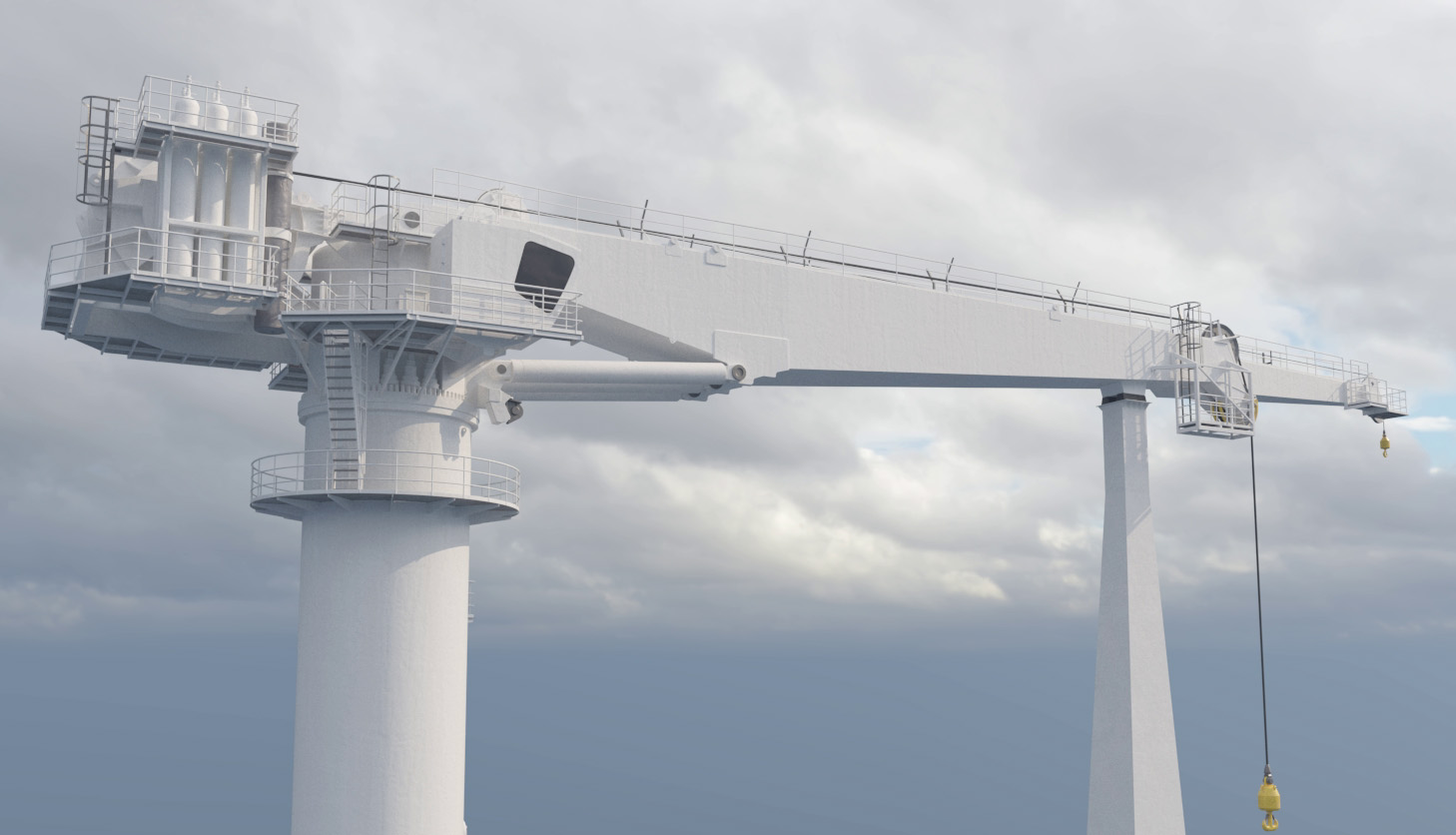
The example shown here, a large offshore crane to be used on a construction vessel, is modelled to a good standard such that it visually represents the real crane but omits the smaller insignificant details in favour of a shorter turnaround time and an appearance that is more than adequate for rendering when needed.
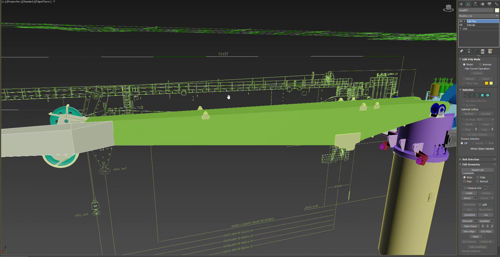
Each required element is modelled using basic splines, extrusions and lathes but overall, the effect is to create a convincing form that is rigged and ready for animation maintaining real world degrees of motion.
2. Survey data as a source
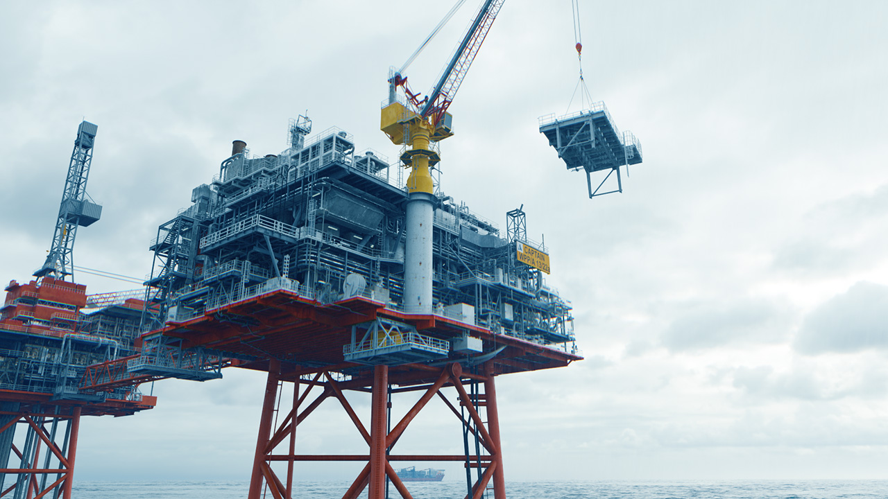
Many assets, both vessels and offshore platforms where cranes are installed often have extensive survey data available. This can be in the form of either tripod style laser scans or drone based photogrammetry. Both cases are ideal for import to 3ds Max for use as a basis for modelling. These point clouds then sit within the 3D space, at real world units, and modelling can be completed in and around those survey points. The point cloud acts a full 3D capture of the crane and allows for a very good representation to be created using relatively simple modelling methods.
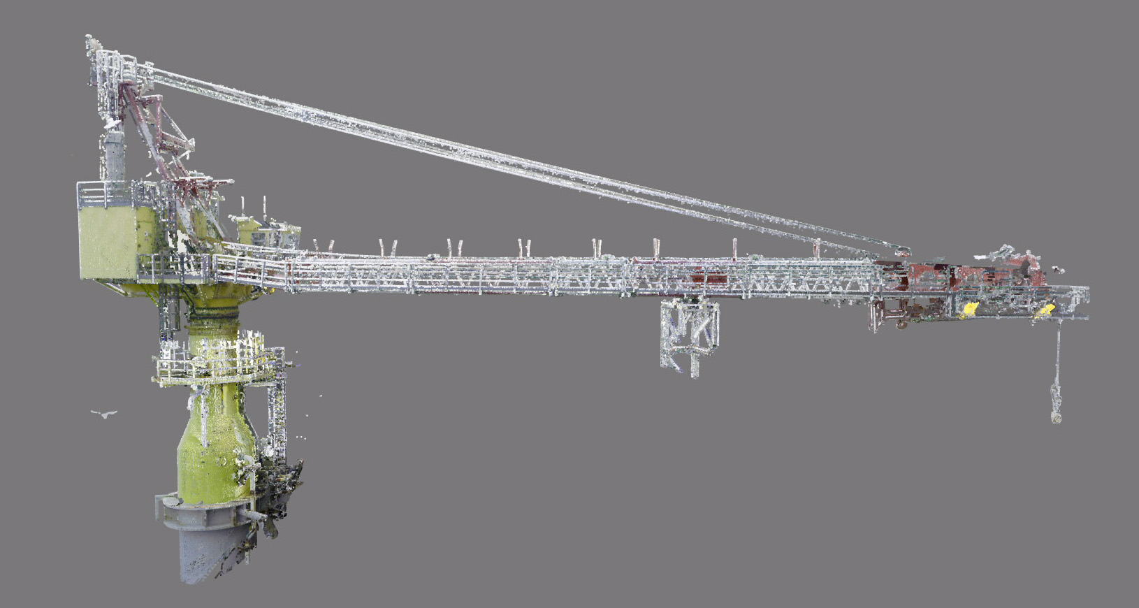
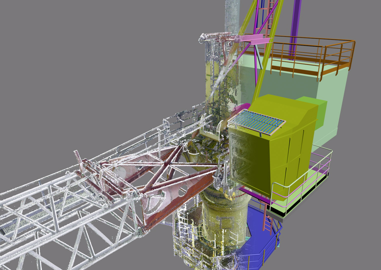
Most of the shapes can at least start out as tracings of metal plates and extruded to thickness. Other elements can start out as cylinders and cubes, with some sub editing where needed.
The advantage of modelling the crane based on the survey data is that the crane can then be rigged to move, slew and lift objects allowing for clash checks, crane tip proximity checks, hook height checks and more. The original point cloud survey data is of course static and can’t ‘move’ or change its state. Further to this, appropriate materials and colours can be applied to the crane model to allow for higher quality rendering and visuals if needed.
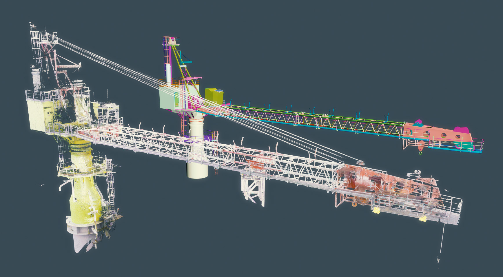
This is a great way of utilising expensive survey data, that tends to be viewed online only (or via particular software) and generates added value where usable 3D assets can be generated and operated in a virtual sense at scale and with accurate representation.
Other sources and LOD (levels of detail)
Very simplistic representations of cranes are sometimes included in larger Navisworks files, whether for a boat or platform/semi-sub. However the cranes are usually only placeholders with an overall shape being extruded from a single profile (for the main boom, knuckle boom etc) and not in a state suitable for rigging. The reason being that cranes are provided by a separate supplier to the main asset and are fitted at a later date, so not included in the fabrication yard Navisworks file.
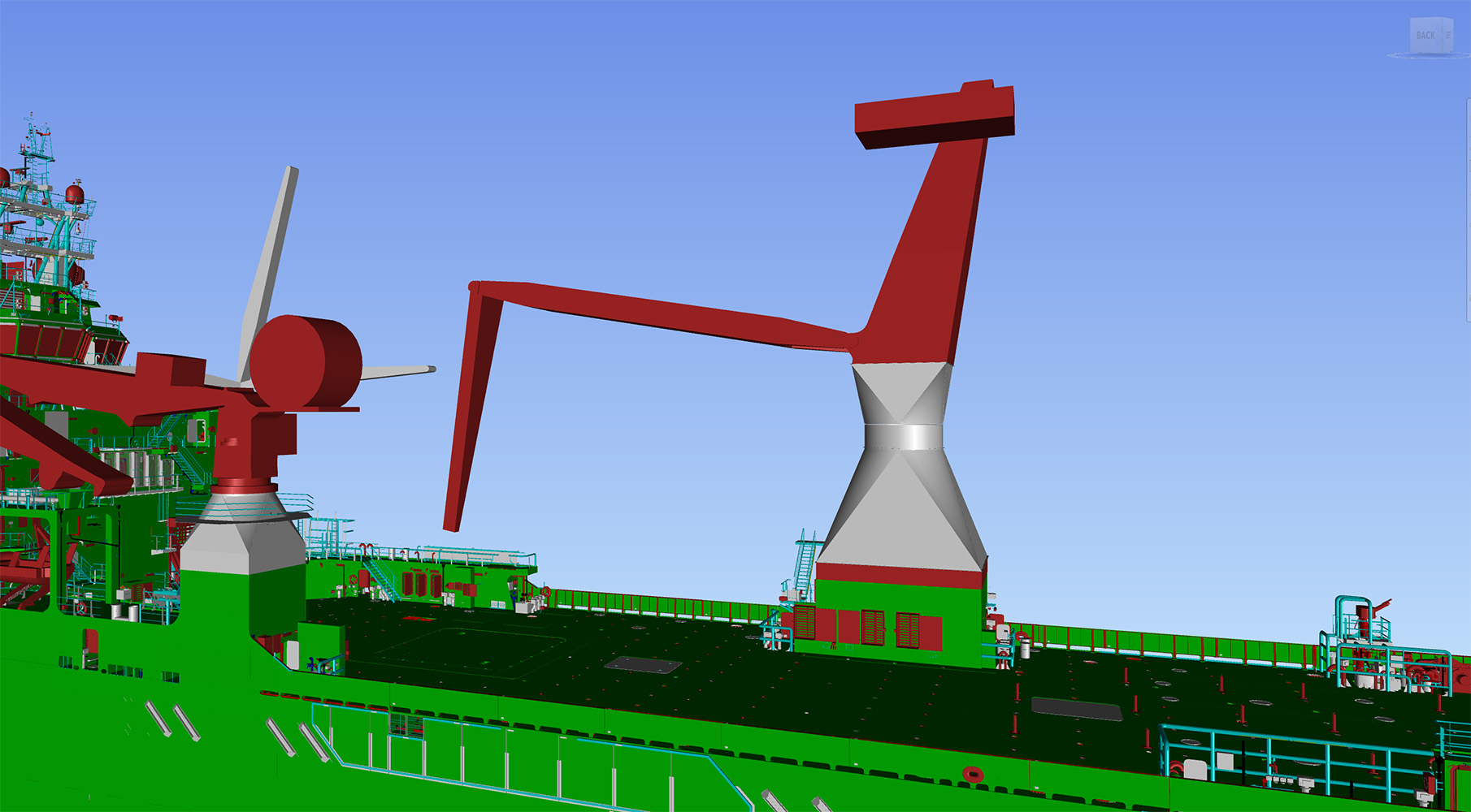
The task there is then to develop this from what info exists, either supplemented with drawings or sizes or perhaps photographs of the real thing. The key information is of course the position of the pivots for the boom and swivels. With that, the rest of the crane can form around it and better represent the crane in use.
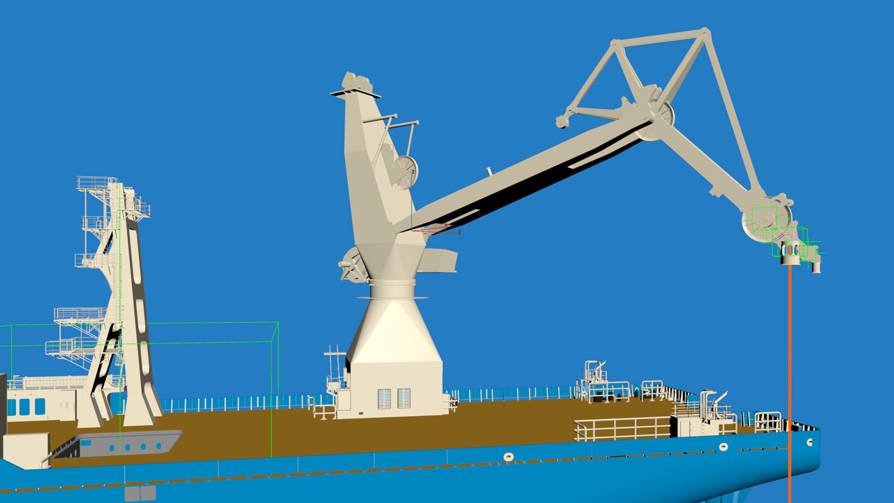
Again, the time available for modelling here is dependent on the available information or data as well as the budget for the 3D build. In all cases, the end result can be tailored to result in the most effective model that can as a bare minimum move as intended with hooks and wire ropes.
Crane models are perhaps the most vital element of an animation where assets are being lifted and deployed offshore or subsea. Time can be critical and so the crane model itself can be very simply represented, as long as the main pivot points are where they need to be. This means that basic block shapes can be used to visualise the crane and its boom and rigged for operation. In the example below the initial work was carried out using a very basic version of the crane, however vital details regarding hook height and crane tip clash checks were possible along with sequences showing hand shakes subsea. Later, the model was upgraded for a different purpose where higher quality rendering was required. The same animations were maintained, but the crane was improved along with the rest of the vessel.
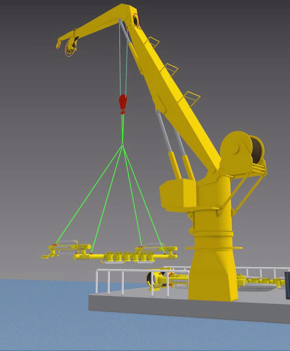
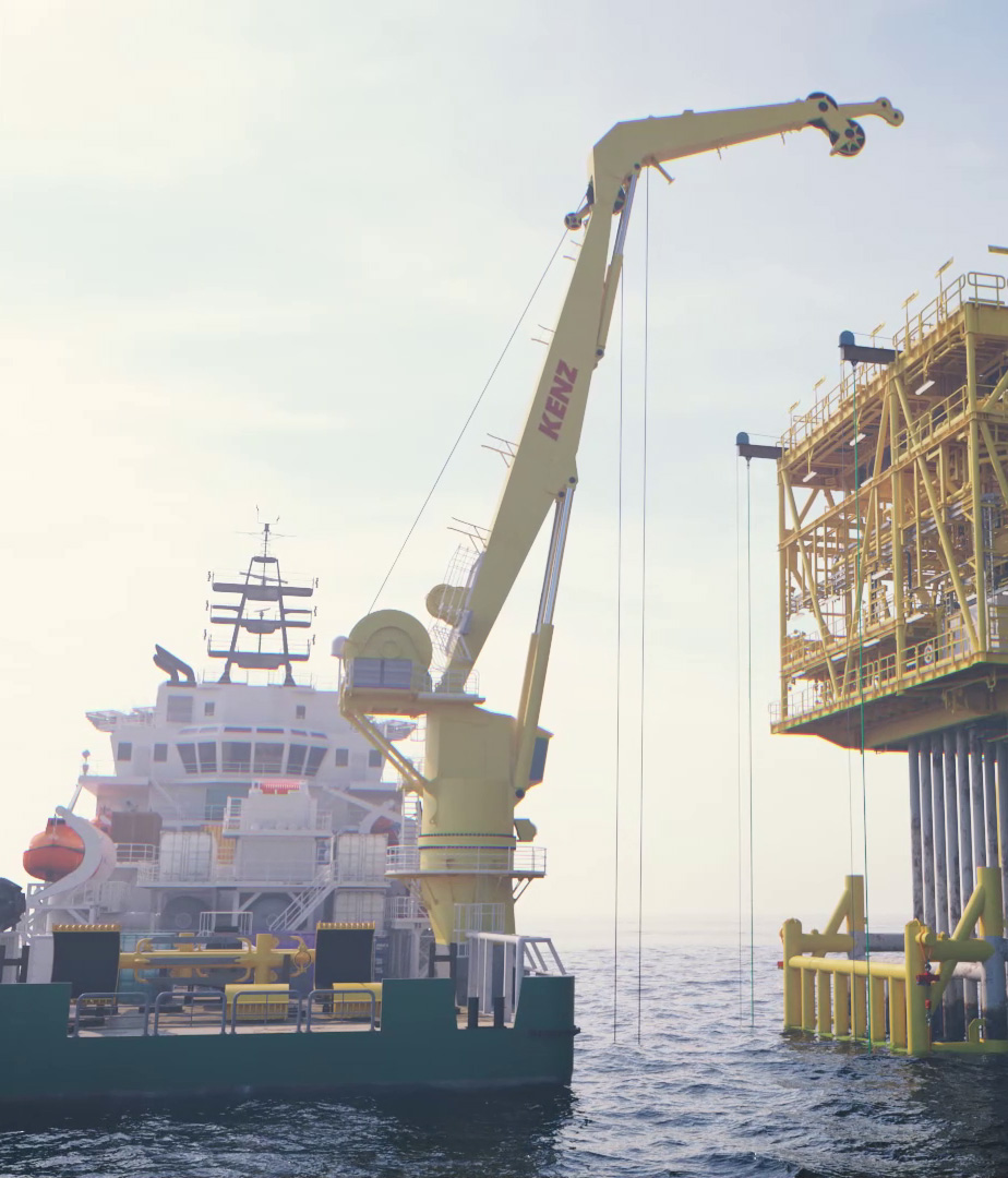
This is a great way of utilising these models, where the overall key engineering work can be carried out at an early stage with simple forms then if needed upgraded with higher detail. That difference in ‘level of detail’ is a key offering at Perspective (Scotland) Ltd and something we would like to discuss when determining the correct approach for animation work.
The video below shows a brief time lapse of modelling a crane based on 2D AutoCAD drawings and how the level of detail can be controlled to match requirements. The result is a 3D model that can be used to demonstrate and check lifts as part of the overall offshore project design and workflow.
This video shows the crane modelled from the point cloud reference and how those primitive objects, extrduded splines and lathed profiles can all come together to form an accurate representation of the crane.