Often the most effective way to demonstrate an offshore or subsea project is to feature the actual vessel performing the deployment or crane operations in three dimensions. With a fully modelled vessel all aspects of the project can be illustrated and clash checks performed both for proximity with floating or fixed assets as well as for deck operations during lifts.
Structure sea fastening, tag lines, crane wire off-lead / side-lead, and above all else the actual lift sequence through to deployment and touch down are all aspects benefiting from a 3D model and animation.
The build stage
In this case study the vessel modelled happens to be an Offshore Support Vessel used in the installation of new Conductor Guide Frames to a Platform Jacket subsea. With these assets modelled various aspects of the project were demonstrated via high quality animation with supporting details derived directly from the 3D space. The following images are taken from various stages of the build and hopefully give some insight into the process of creating the model and how it is derived.
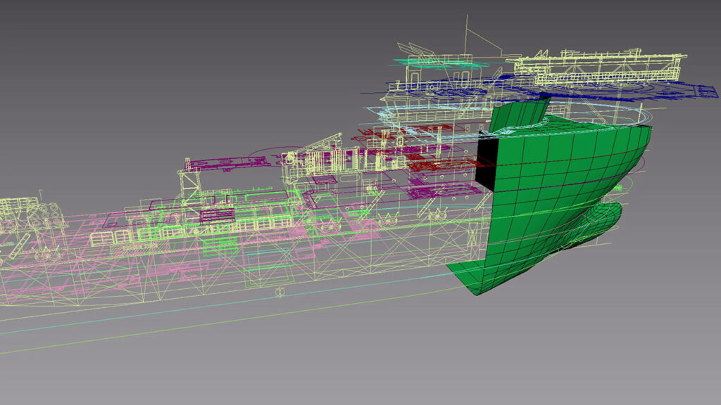
The first stage, as with all 3D modelling tasks, is to set up the references. When working on projects that involve a particular vessel, in most cases a General Arrangement drawing will be provided as a reference to the vessel’s overall design and size. This document will most likely come in the form of a set of two dimensional line drawings depicting the main elevations and deck plans through the vessel. These drawings can then be imported to Autodesk 3ds Max where they can be scaled and aligned in 3D space so as to create a linework visual reference of the overall form.
The hull is developed by generating a surface mesh using the 2D drawings as a guide, with the detail being kept to a minimum where possible for efficiency both in the model itself and in time. The focus for use in animation is most commonly on the main deck and associated cranes therefore most time is spent in these areas.
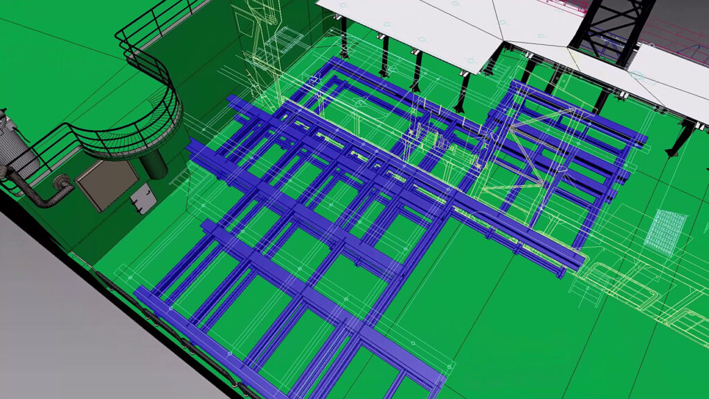
Further increases in detail are added where references allow, and this further enhances the overall quality of the final effect when the key areas are fully fleshed out. In some cases the detail needs to be added with some artistic license as General Arrangement drawings do not tend to include information on main deck equipment and spreads.
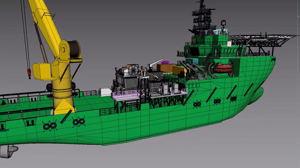
The model is developed largely using straight-forward techniques with Editable Poly objects, Splines with Sweep modifiers and Extrusions from 2D shapes.
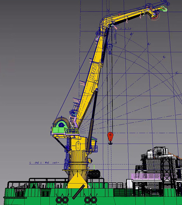
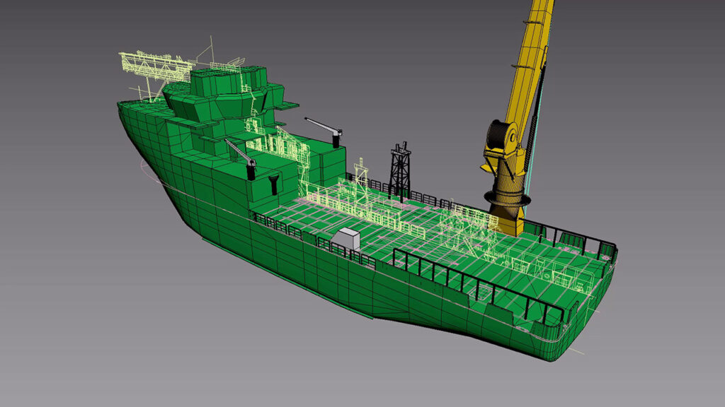
With a larger focus on the key asset, the main crane, more time is spent on modelling the various components paying particular attention to the crane curves (the charts detailing crane reach and hook heights). This ensures that the crane in animation will be representative of its actual capabilities.
Multiple main block configurations can also be set up to allow for single and double fall lifts. With the crane modelled in this fashion it can also be used to check on potential clash checks between the crane boom and the asset where the installation is taking place.
The completed vessel model
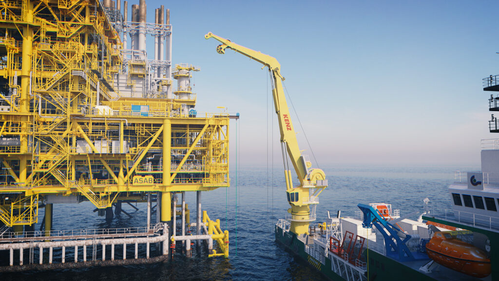
In the fully completed and rendered example, the crane is shown operating in close proximity to the fixed topsides and dimensions are supplied to the client illustrating the distances between the crane/tip and various points on the platform.
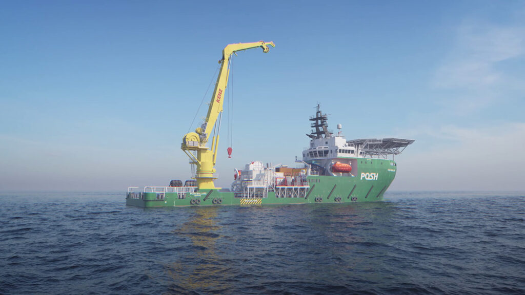
The model is “painted” with appropriate colours and materials ready for use in rendered animation work, where required. The benefit moving forward is that the model can be used in future projects and helps promote both the direct work being carried out but also gives the Team (onshore and offshore) and the Client a better understanding of the proposed processes and deployments.