When presented with the opportunity to 3D model an offshore field and any installation or recovery projects that are to be carried out in its development, there can be key differences between how to approach the work depending on the status of the field overall. In most cases, with modern or greenfield developments, there can be large amounts of 3D CAD data available along with comprehensive AutoCAD drawings and information on the new assets.
With brownfield sites the information can be limited (due to changes in Operators over time and lack of access to source material) and can often come in the form of older, scanned drawings and PDFs. Regardless of the sources, high quality models and animations can be produced and the following steps give some insight into recently created work for such a brownfield development.
References
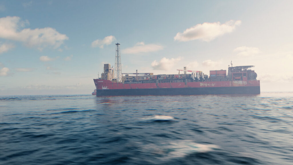
The first step is assessing what information is available and to what extent it can be used to act as a reference in building 3D models. Existing photos of assets and vessels are also helpful and can be used directly in the modelling work. In the case highlighted here the older CAD drawings were only available as scanned versions in low quality. The views available were extracted from the PDFs and aligned in 3D space along with the various other orthographic views of the subsea structures that were needed for the project.

Often with scanned drawings, the views tend to be warped to some degree and corrections are required to re-straighten the longer edges and then also check for scale using known dimensions.
Sketching out the models
The drawings are aligned in 3D space, using Autodesk 3ds Max as the main modelling tool, and scaled up to their real-world size. All scenes in our work are completed at 1:1 scale to make them both compatible with each other across projects but also such that they are compatible with CAD drawings, survey data and point clouds, as well as client supplied STEP files and NavisWorks projects.
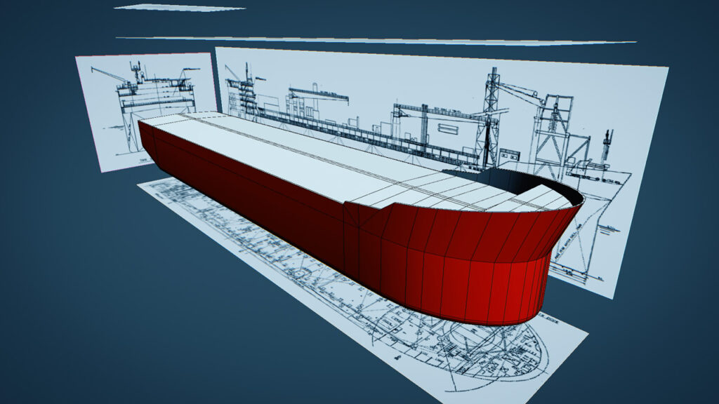
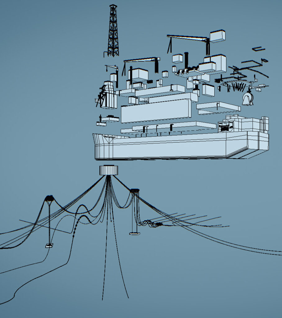
Starting with the larger entities such as the main hull, the various surfaces are sketched out and developed utilising the CAD drawings as a guide. Details are kept low at this stage such that the overall form can be created quickly resulting in a representation of the FPSO based on the information available. The overall aim here is to build a model suitable for use in the animation work that can be used for vessel proximity checks and other key tasks but that is achievable within the budget allocated.
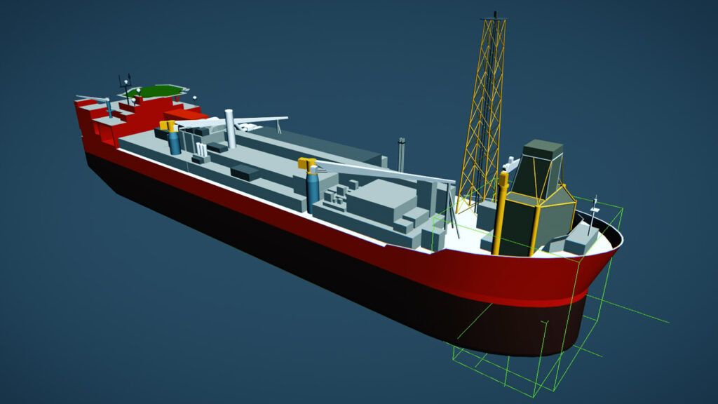
The completed base model includes the main features of the FPSO and visually demonstrates the general form and footprint without needing to include the fine details found across the main decks and topsides of such vessels. The focus of the project was to be on the subsea layout and direct areas near the underside of the Turret and so that is where the majority of the modelling time was spent.
Adding value
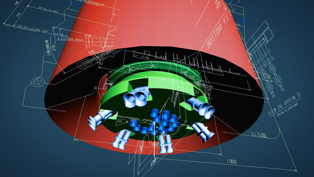
For those areas of interest, further CAD drawings were brought into the 3D scene and used as a basis for modelling – in this case Fairleads, Riser bell mouths and I Tubes as well as Riser Hang-Off structures and components at the topsides. This approach to the work ensures that there is more time spent where it adds value to the animation and is concentrated in areas with greater focus for the project. These elements are built in the same space as the larger assets and therefore seamlessly fit in with the wider 3D scene.
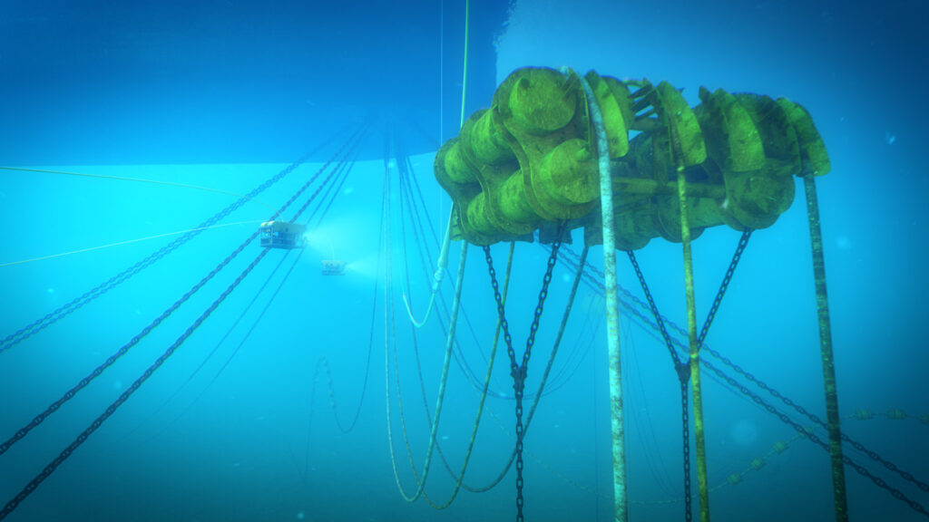
The process then moves further upstream to the subsea field architecture (all existing) where appropriate drawings are used to model those elements such as the Mid-Water Arch shown below. Again, there is limited information for the structure, however even with only three technical views a model can be created which is accurate to the overall dimensions and adequate for the animated sequences to come.
Risers and Umbilicals are modelled into the scene to connect the seabed structures to the FPSO via the Mid-Water Arch and this is repeated for the remaining items to be included in the scene.
Scene assembly
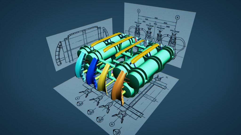
Using field layout drawings as a guide, the various elements are positioned and aligned to form the bigger picture. Catenaries for the Risers and other flexibles are positioned referencing the drawings and section lengths including models for their respective Buoyancy Modules and Bend Stiffener elements.
Prior to moving onto the next stage, the various items in the scene can be ‘painted’ with appropriate materials and finishes. These materials can be based on options from libraries or derived from photographs of the actual assets. This further enhances a sense of realism in the presented work in comparison to the bare bones appearance of the models during construction. The image to the right shows an exploded view of the model highlighting the various items requiring further work and painting, depending on the intended level of quality of the final rendering.
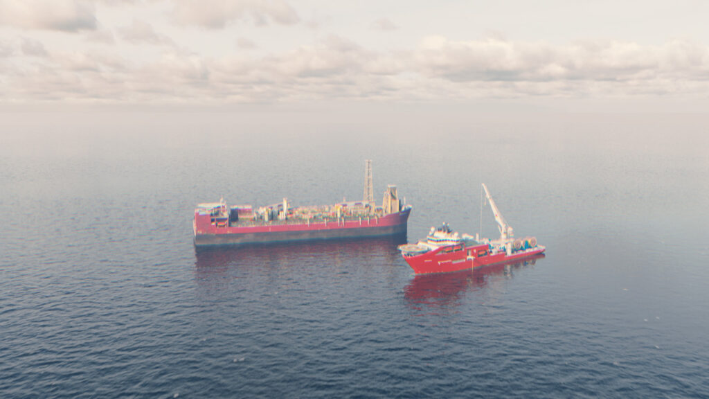
Here the Construction Vessel has been added to the scene alongside the FPSO, with the various items modelled and included in greater detail on the main deck ready for animation with the cranes.
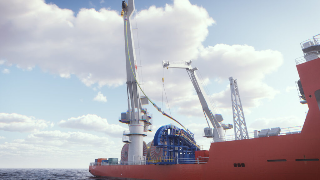
Planning crane ops
A key feature of the animation work is in showing how the flexible product is to be lifted and deployed overboard as planned by the Engineers, in this case using two cranes. Being able to visualise these lifts and crane movements in three dimensions along with a fully modelled representation of the vessel helps highlight risks and confirm crane reach and hook height positions as well as confirm rigging lengths and their arrangements.
Moving below the surface, images can be provided showing the installation sequence and how much space and access is required for both the Product being installed as well as the ROVs manoeuvring around existing features such as the mooring lines. In the scenario shown the crane is still supporting the Riser and must be disconnected by the ROV.
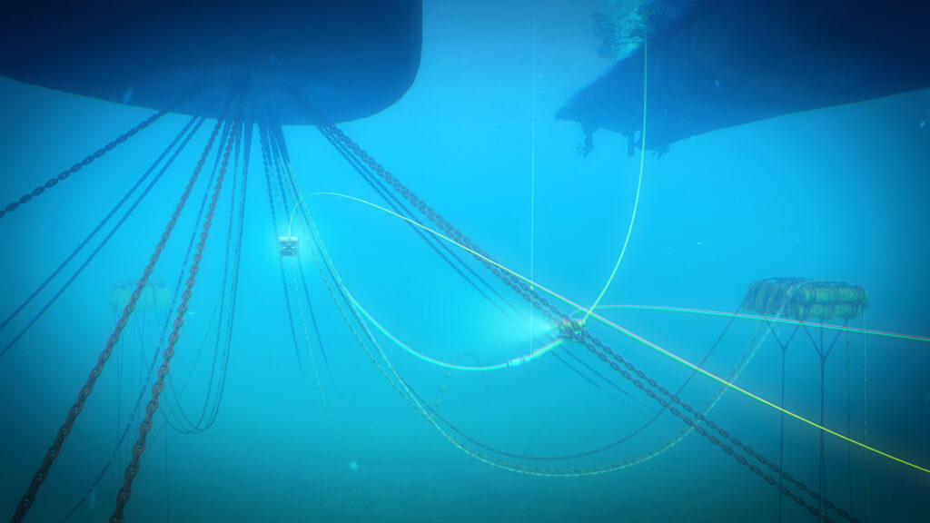
Demonstrating installations
The importance of including all of these elements is clear when it comes to checking for clearances and proximities between the various assets and the recovery/deployment vessel and their ROVs. Being able to demonstrate the proposed activities in a 3D space is incredibly useful as it highlights potential issues early in the planning process and allows for changes to be made and checked as that plan evolves.
Moving forward, the scene can be revisited to add additional items or showcase future works with the 3D model developing as the field develops.
Visualising the project
The final product can be packaged as a high quality rendered video, combining models of lower and higher detail to suit the requirements of the project as well as the available budget. In all cases, and in this example highlighted, by using 3ds Max as a tool for bringing together various digital assets such as CAD drawings, engineering models, survey data and site photos we end up with a single point of visualisation that can be used in multiple ways. Lift plans and deployment procedures can be developed within a fully modelled 3D environment covering activities both at the surface and subsea.
If you’d like to see a short presentation video on this project please use the link below to visit LinkedIn along with other posts covering similar topics.